FIG. 03 · TELEMETRY ANTENNA MOUNTS · RICE ECLIPSE
rocket telemetry antenna mounts
designed, prototyped, and field-tested two antenna mounting systems for rice eclipse rocketry, an omnidirectional mount and a directional yagi with 0–90° tracking. all 7 design criteria met or exceeded.
the problem
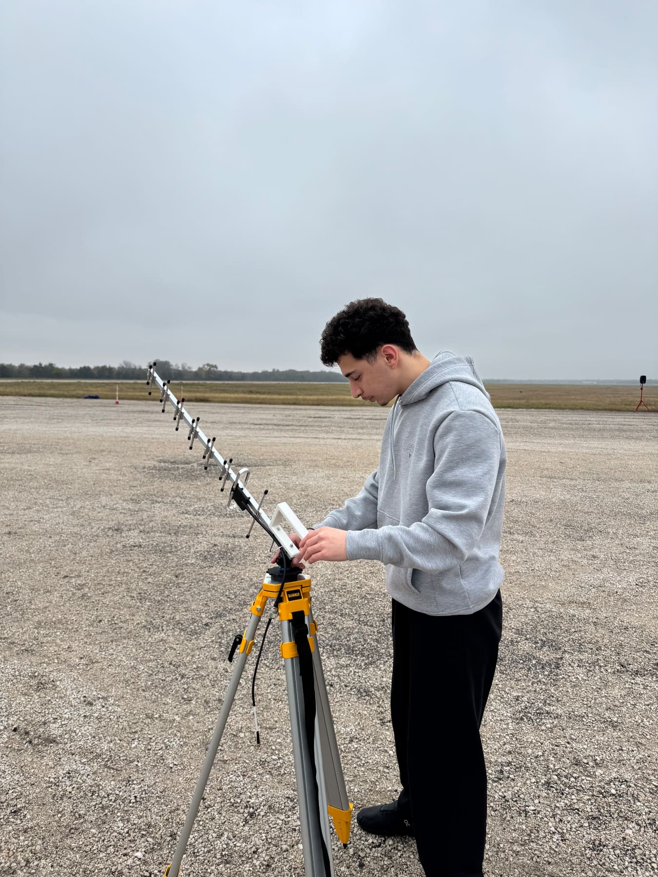
as part of rice eclipse’s telemetry team (the teletubbies), i worked with four teammates to solve a critical problem: their current antenna setup was improvised, unstable, and limiting their ability to maintain communication with rockets during launch. antennas were literally taped to random objects, and the yagi directional antenna had to be manually held throughout entire launches: exhausting and imprecise.
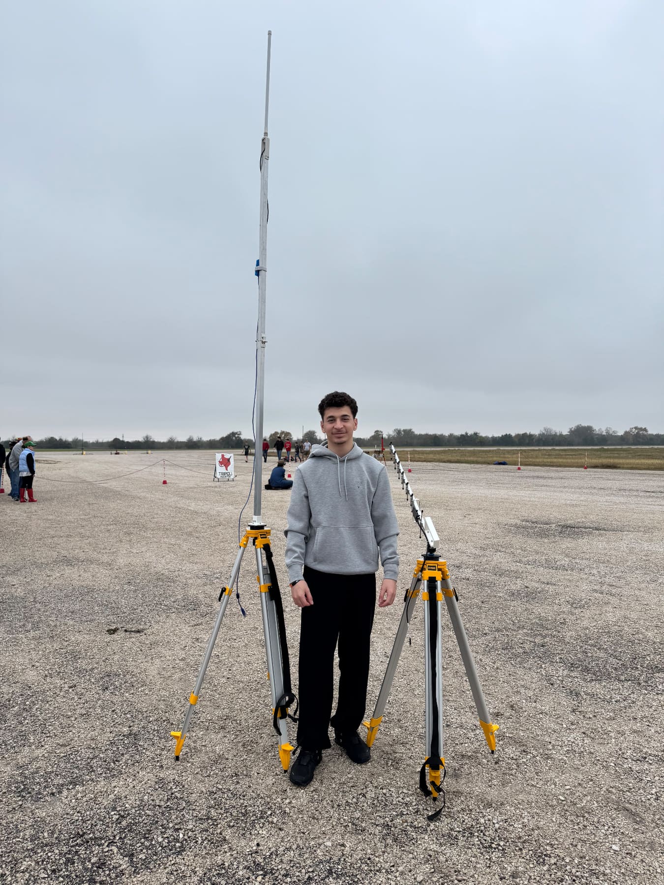
our challenge was to design professional mounting systems for two different antennas: an omnidirectional antenna that needed to reach 10+ ft to clear obstacles, and a yagi directional antenna that operators could smoothly track from 0° (horizontal) to 90° (vertical) as the rocket ascended.
the client
rice eclipse is the university’s competitive rocketry club. their 2024 launch hit 25,163 ft. the goal: 100,000 ft, which requires flawless telemetry the whole way up.
- 25,163 ft
- 2024 LAUNCH ALTITUDE
- 100k ft
- TARGET ALTITUDE
- 18–20 mph
- LAUNCH SITE WINDS
- 180°F
- MAX TEMPERATURE
current limitations
- height. antennas taped to random objects couldn’t clear the 10-ft canopy → reduced signal range
- stability. yagi manually held throughout launch → physically demanding and imprecise
- repeatability. each launch required a new improvised configuration
- wind resistance. setups prone to tipping in 18-20 mph midland winds
understanding the antennas
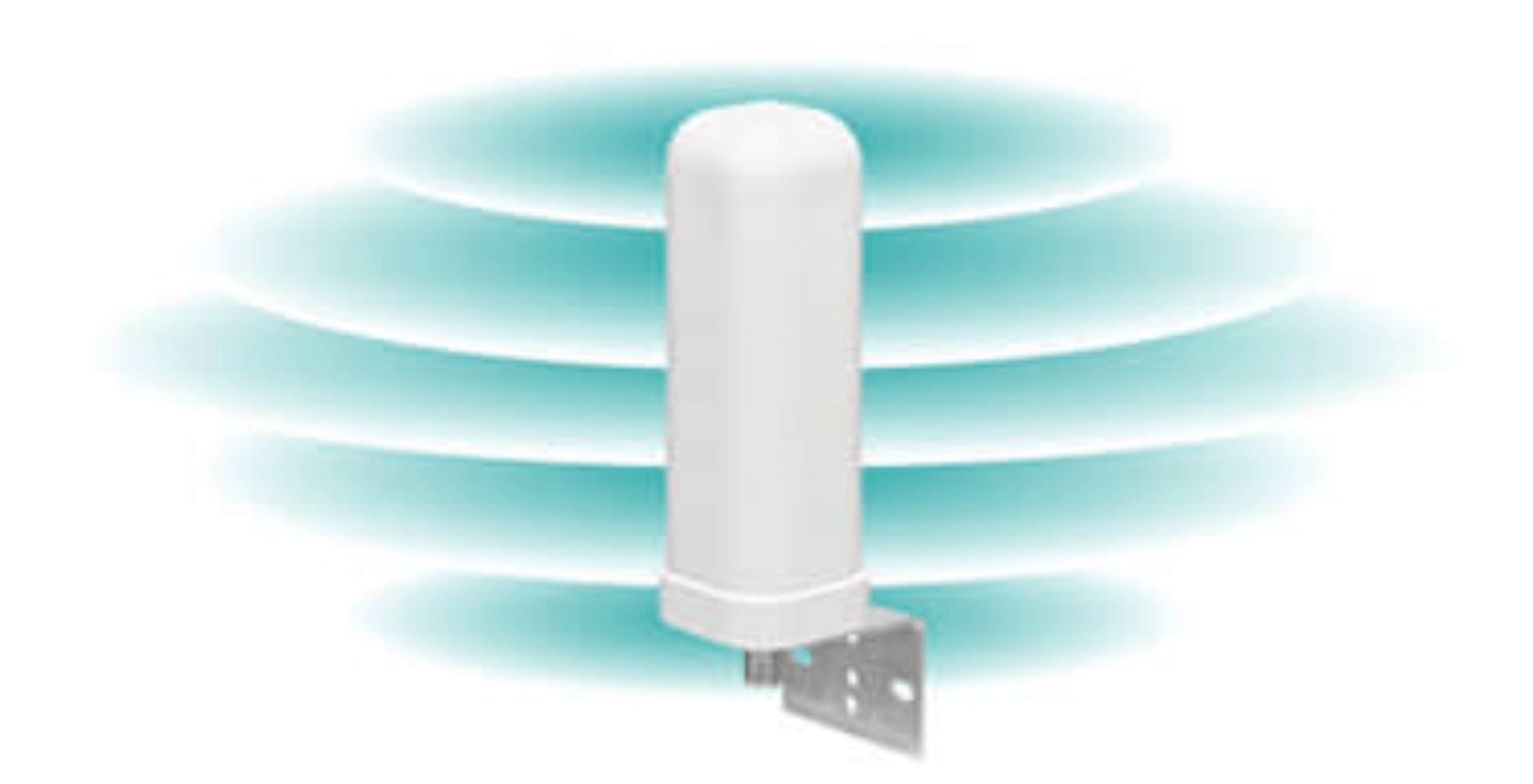
omnidirectional (omni)
receives signals in a 360° horizontal radius with a blind spot directly above. can stay stationary once positioned. needs ≥10 ft elevation to clear obstacles.
yagi
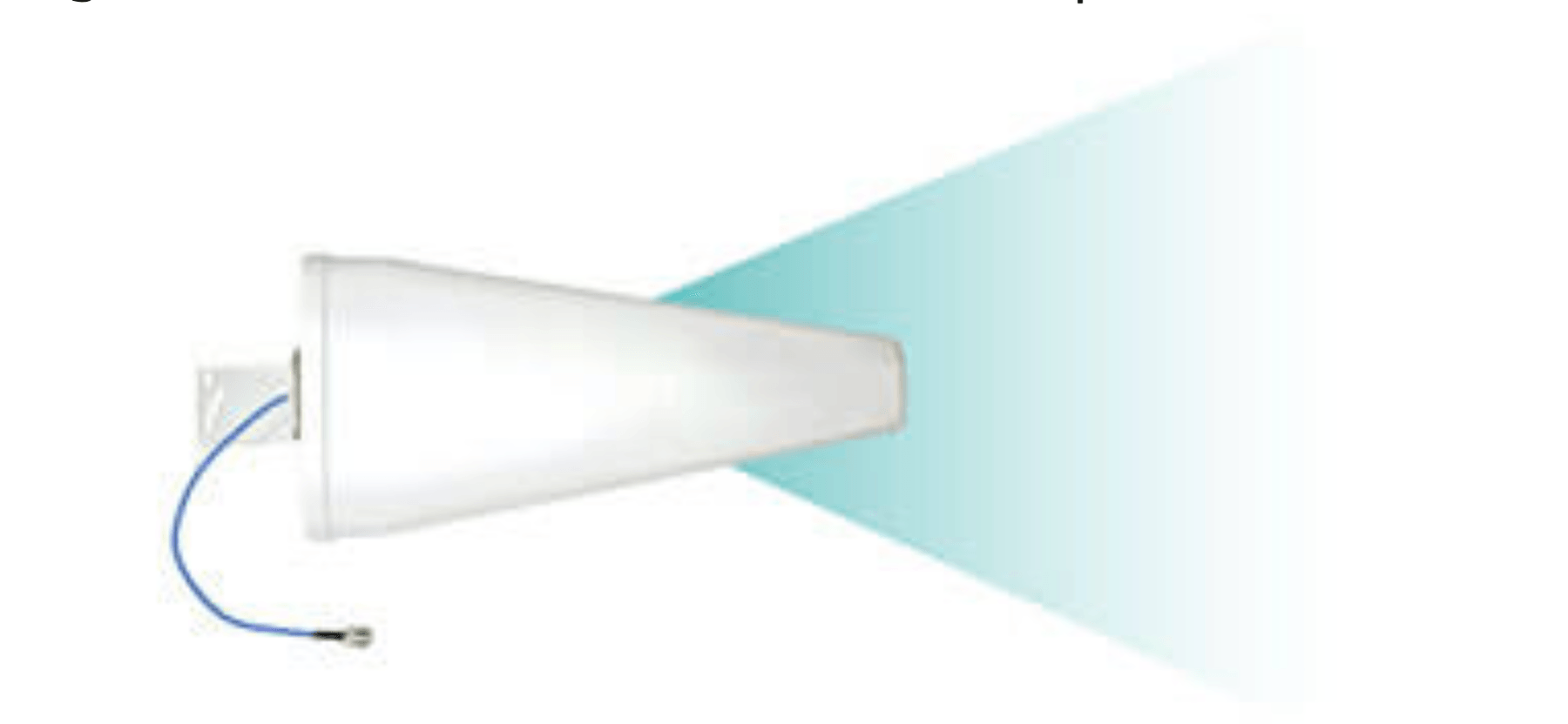
receives only from the direction it’s pointed, in a narrow cone. must rotate from 0° to 90° to track rocket ascent. requires precise aiming throughout launch.
design criteria
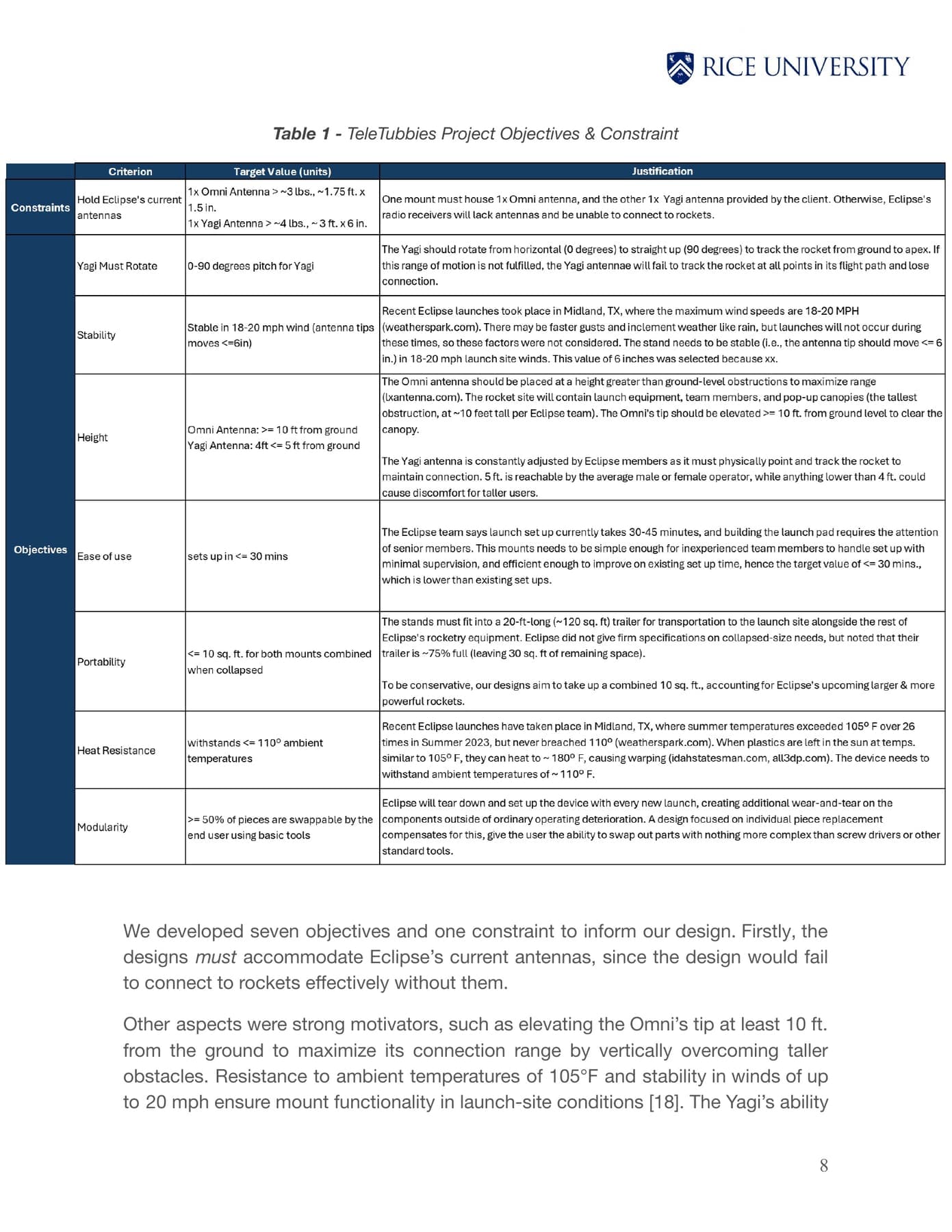
working closely with eclipse, we set one constraint and seven design objectives, then prioritized them using pairwise comparison.
constraint
hold current antennas: must accommodate 1× omni (≥3 lb) and 1× yagi (≥6 lb) and interface with eclipse’s existing equipment.
objectives (prioritized)
| RANK | CRITERION | TARGET | WHY |
|---|---|---|---|
| 1 | stability | antenna tip ≤8" movement in 18-20 mph wind | movement disrupts connection |
| 2 | rotation | yagi rotates 0–90° vertically | must track from ground to apex |
| 3 | height | omni ≥10 ft, yagi 4–5 ft | omni clears canopy, yagi at operator height |
| 4 | ease of use | setup ≤30 min | launch prep is already 30–45 min |
| 5 | portability | collapsed ≤10 sq ft | must fit in 20×10 ft trailer |
| 6 | heat resistance | withstands ≥180°F | midland temps, materials must not deform |
| 7 | modularity | ≥50% replaceable parts | enables maintenance |
design process
problem decomposition
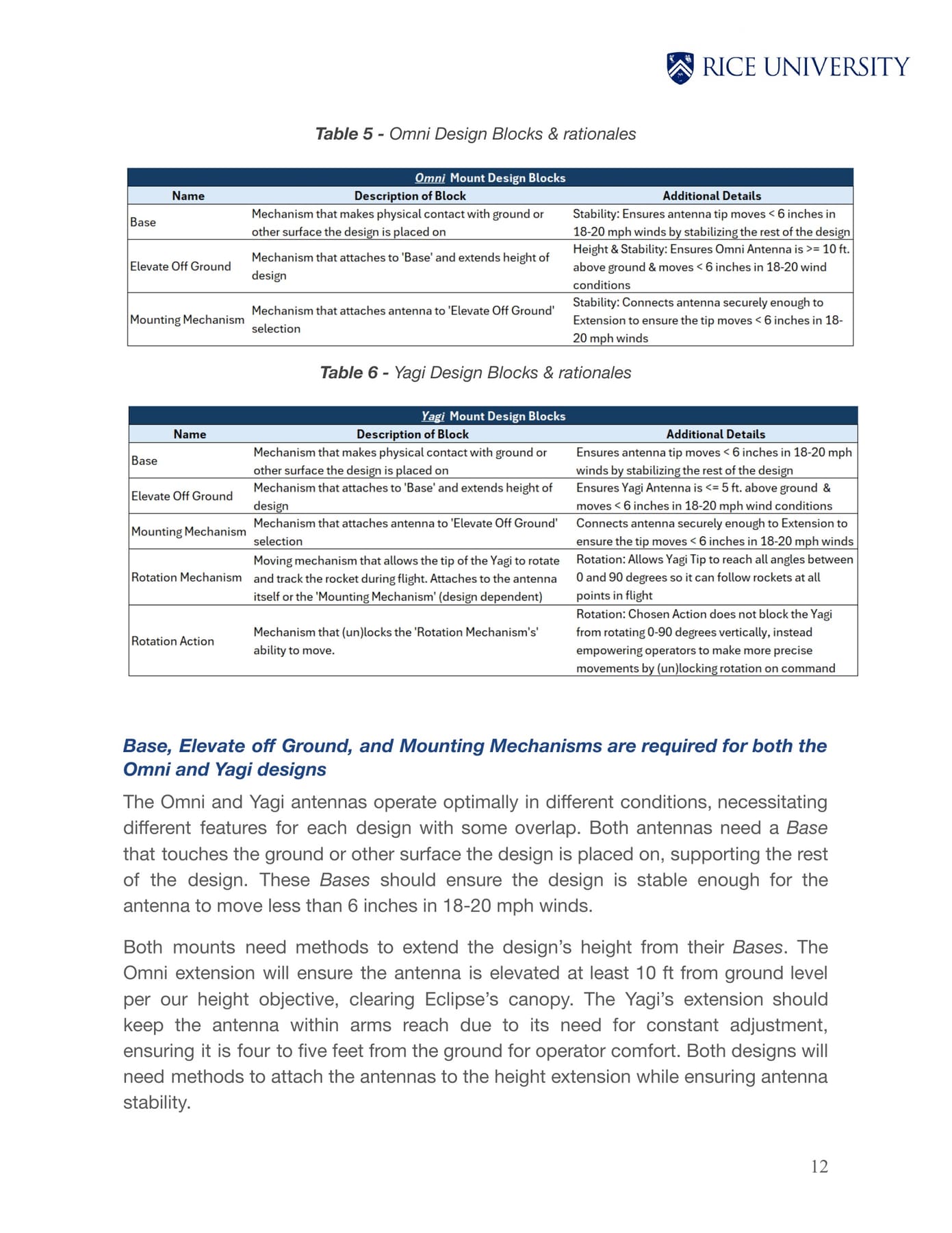
broke the challenge into functional “design blocks”:
- base: physical contact with ground, provides stability
- elevate off ground: extends height to meet requirements
- mounting mechanism: securely attaches antenna to structure
- rotation mechanism (yagi): moves the antenna tip 0–90°
- rotation action (yagi): how the operator controls / locks rotation
brainstorming + concept development
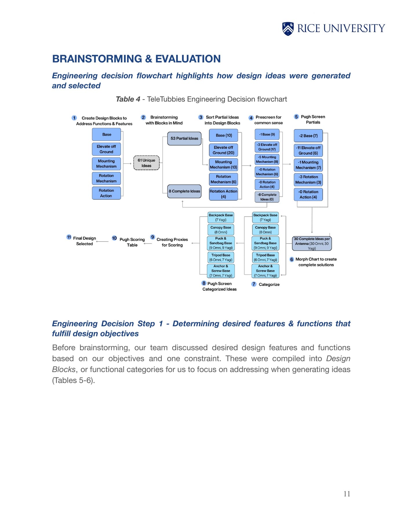
systematic engineering decision process:
- create design blocks based on required functions
- brainstorm ideas for each block (2 rounds)
- screen partial ideas using pugh charts
- morph surviving partials into complete designs
- categorize complete designs by base type
- screen complete designs using pugh charts
- score finalists using weighted criteria
- select optimal design
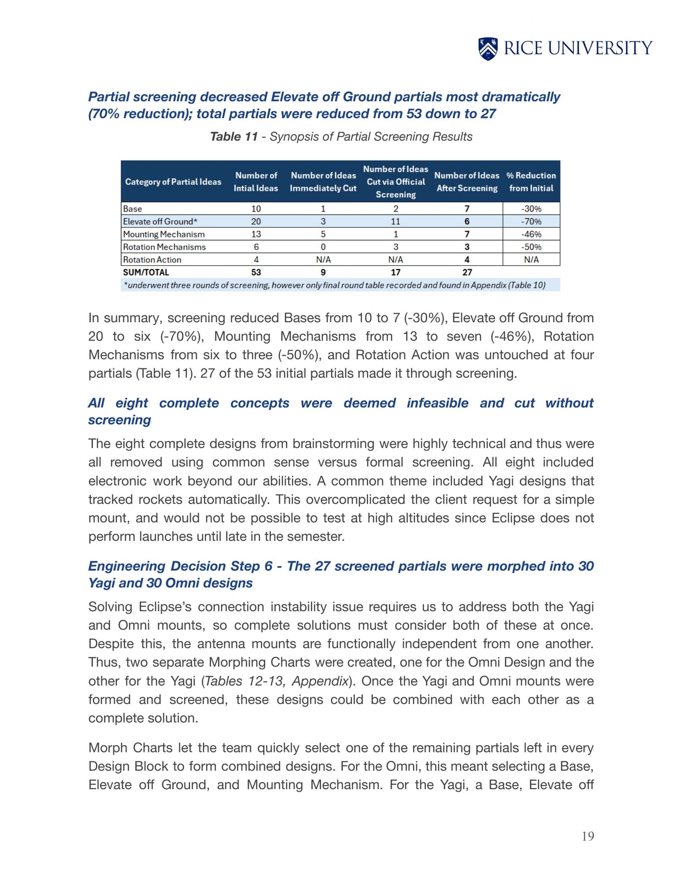
brainstorming results: 61 unique ideas → 8 complete concepts + 53 partial concepts.
screening + morphing
pugh screening eliminated suboptimal partial ideas:
- bases: 10 → 7 (removed suction cup, rubber mat)
- elevate off ground: 20 → 6 (removed scissor lift, motorized slide, rack & pinion)
- rotation: 6 → 3 (removed belt & pulley, axis switches)
- mounting: 13 → 7 (removed friction-fit, bendy clamp)
from the 27 screened partials → 30 omni mount designs + 30 yagi mount designs.
final selection
after pugh screening, 8 finalists (4 omni, 4 yagi). weighted scoring picked the winners:
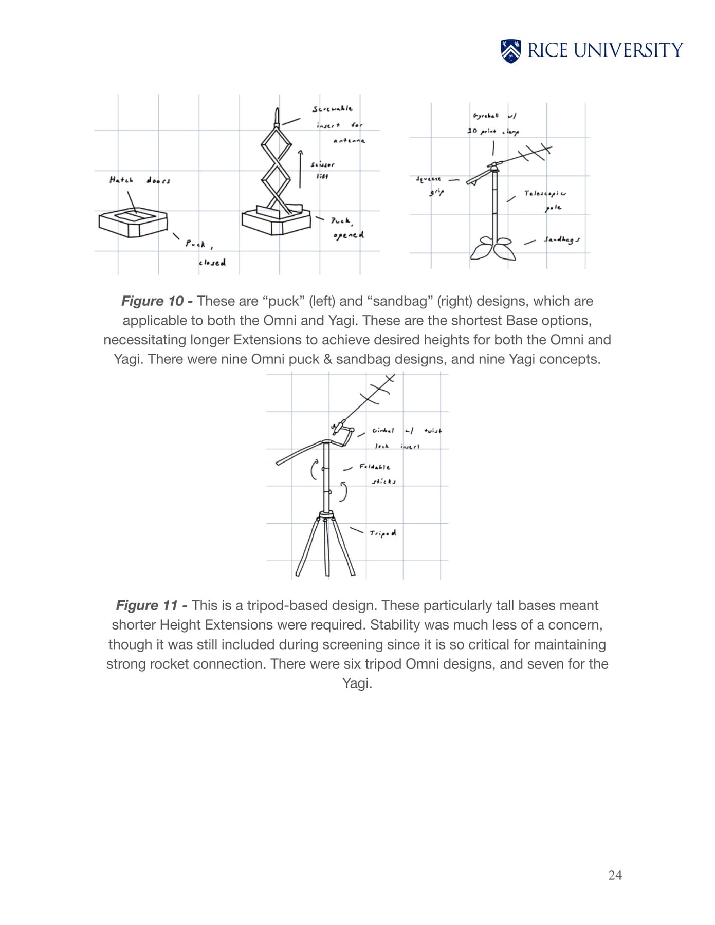
- omni (3.7/5.0): tripod base + foldable sticks (10 ft) + threaded insert mounting
- yagi initial (3.85/5.0): backpack base + telescopic pole + ball joint rotation
the critical pivot
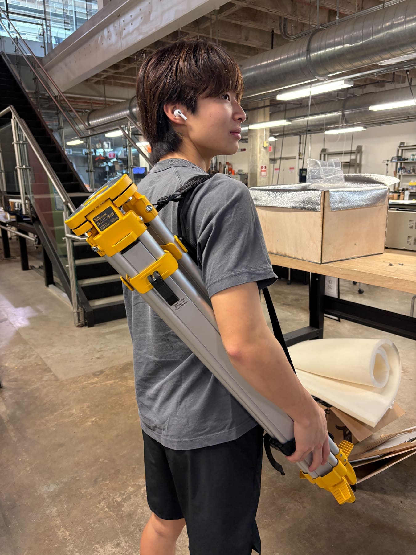
presenting initial concepts to eclipse in october 2024, and got crucial feedback that changed our yagi direction entirely.
final designs
omni mount
- collapsible aluminum tripod base
- foldable wooden sticks extending to 10+ ft
- cam lever hinge locks for quick vertical extension
- threaded insert antenna mounting
- compact collapsed footprint (<10 sq ft)
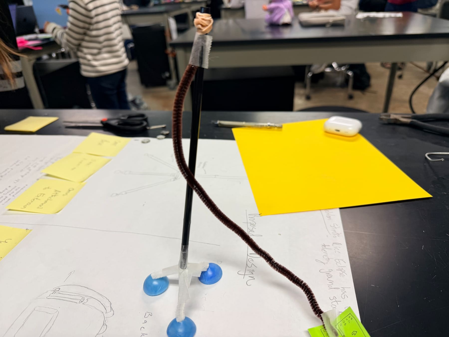
yagi mount
- collapsible aluminum tripod base
- telescopic aluminum pole extending to 5 ft
- free-moving ball joint for 0–90° rotation
- 3d-printed PETG clamp (heat resistant to 230°F)
- ergonomic handle for operator control
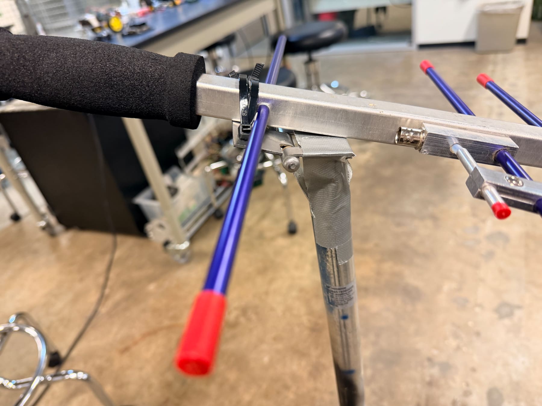
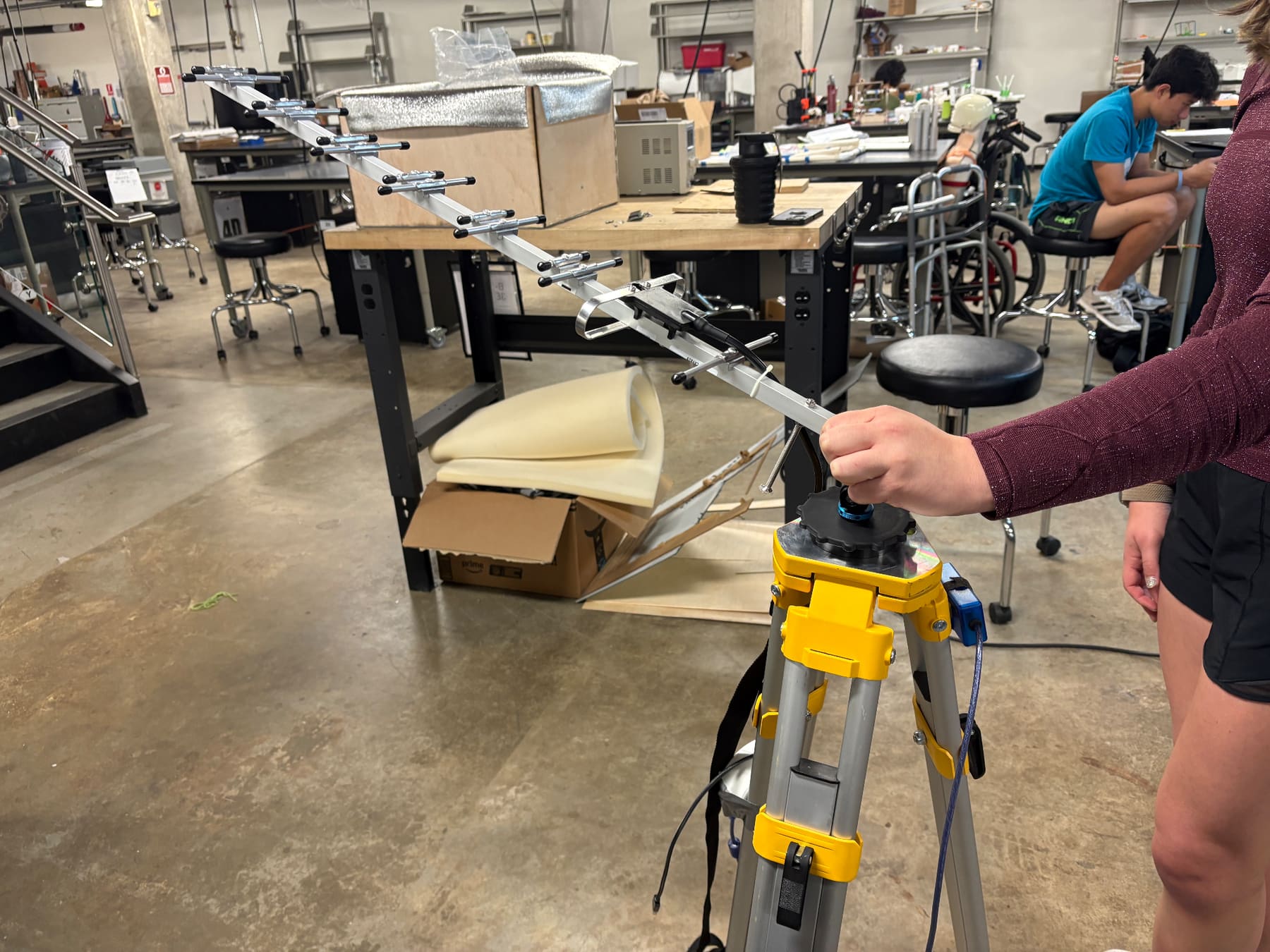
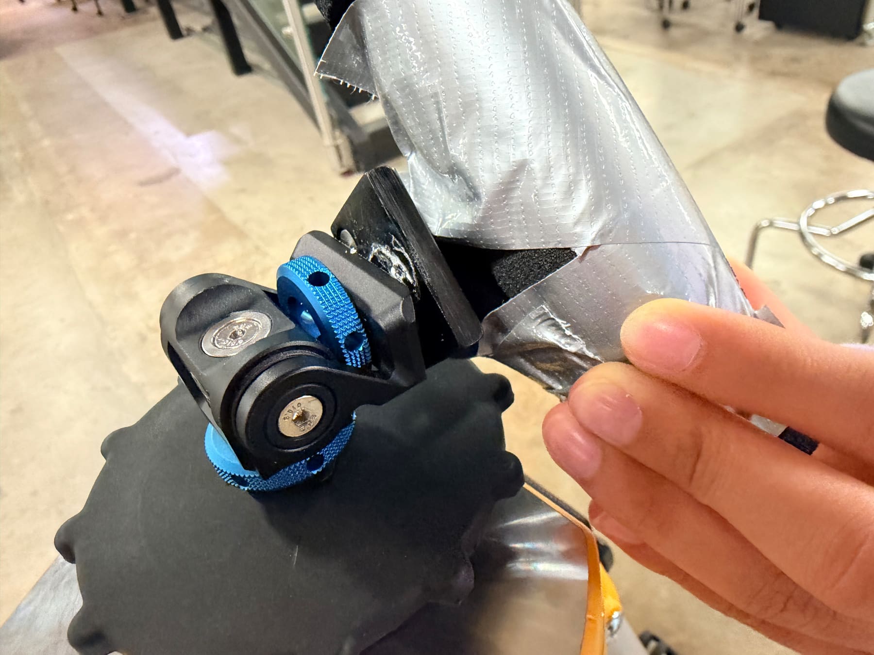
materials: aluminum (tripods + telescopic poles), wood (omni folding sticks), ABS/PETG for 3d printed parts (heat resistant, signal transparent), stainless steel hardware, foam padding for grips.
prototype development
low-fi prototype
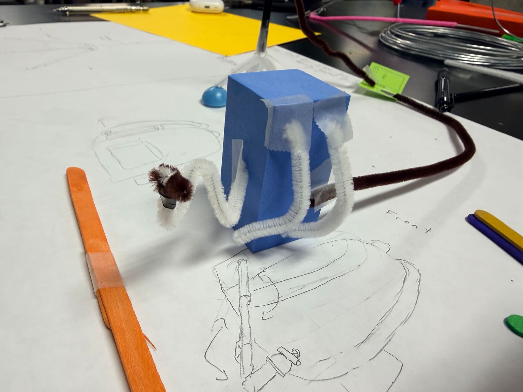
cardboard + foam core + wooden dowels visualized the overall design and verified basic dimensions. confirmed the 10-ft omni height was achievable and that the ball joint gave 95° of rotation.
medium-fi prototype
tested functional materials with real antenna weights:
- ✓ stability: both mounts withstood simulated 20 mph wind with <6" sway
- ✓ height: omni reached 10.5 ft, yagi 4.8 ft
- ✗ setup time: initial assembly took 42 min (target was 30)
hinge mechanism evolution
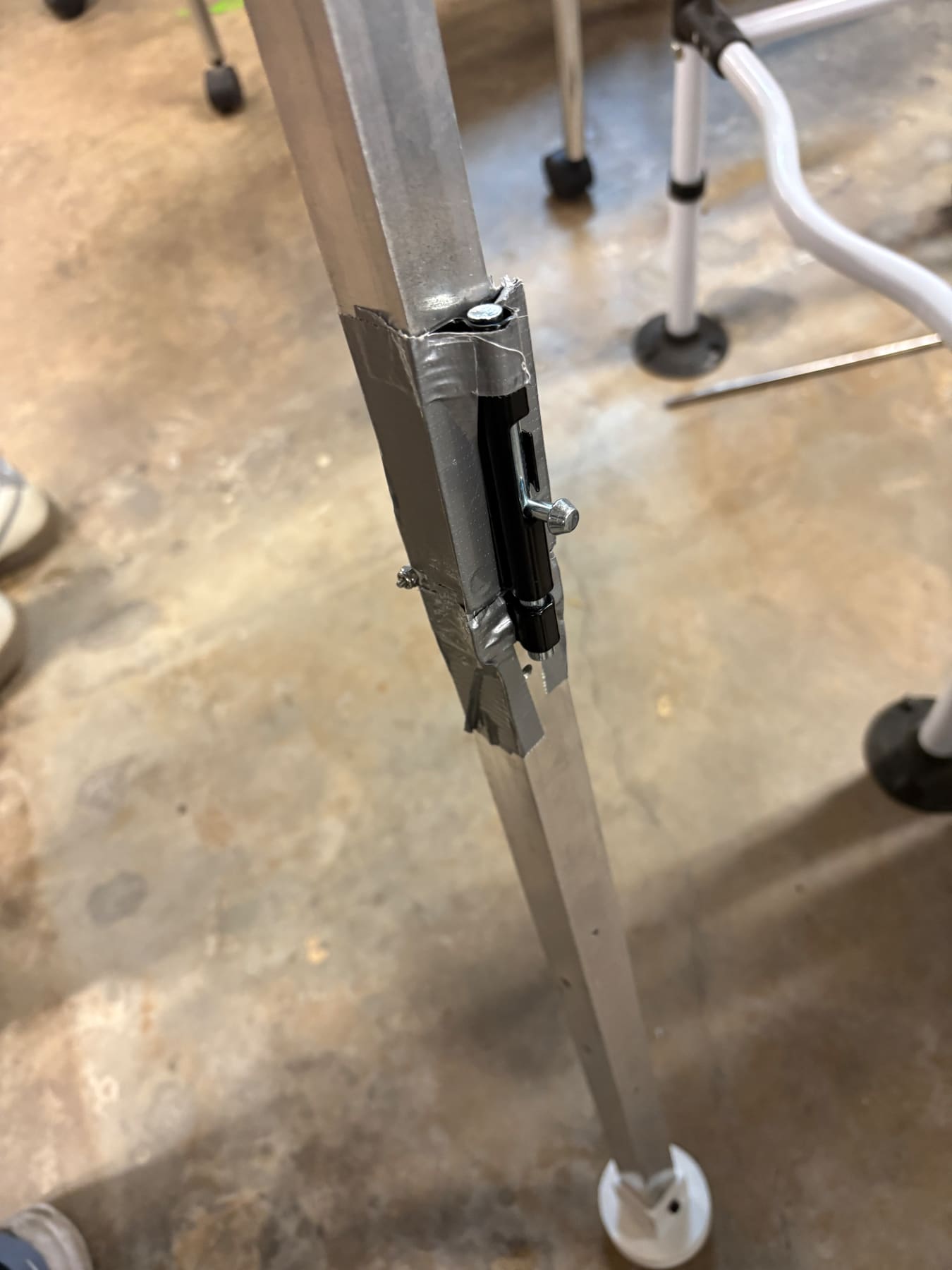
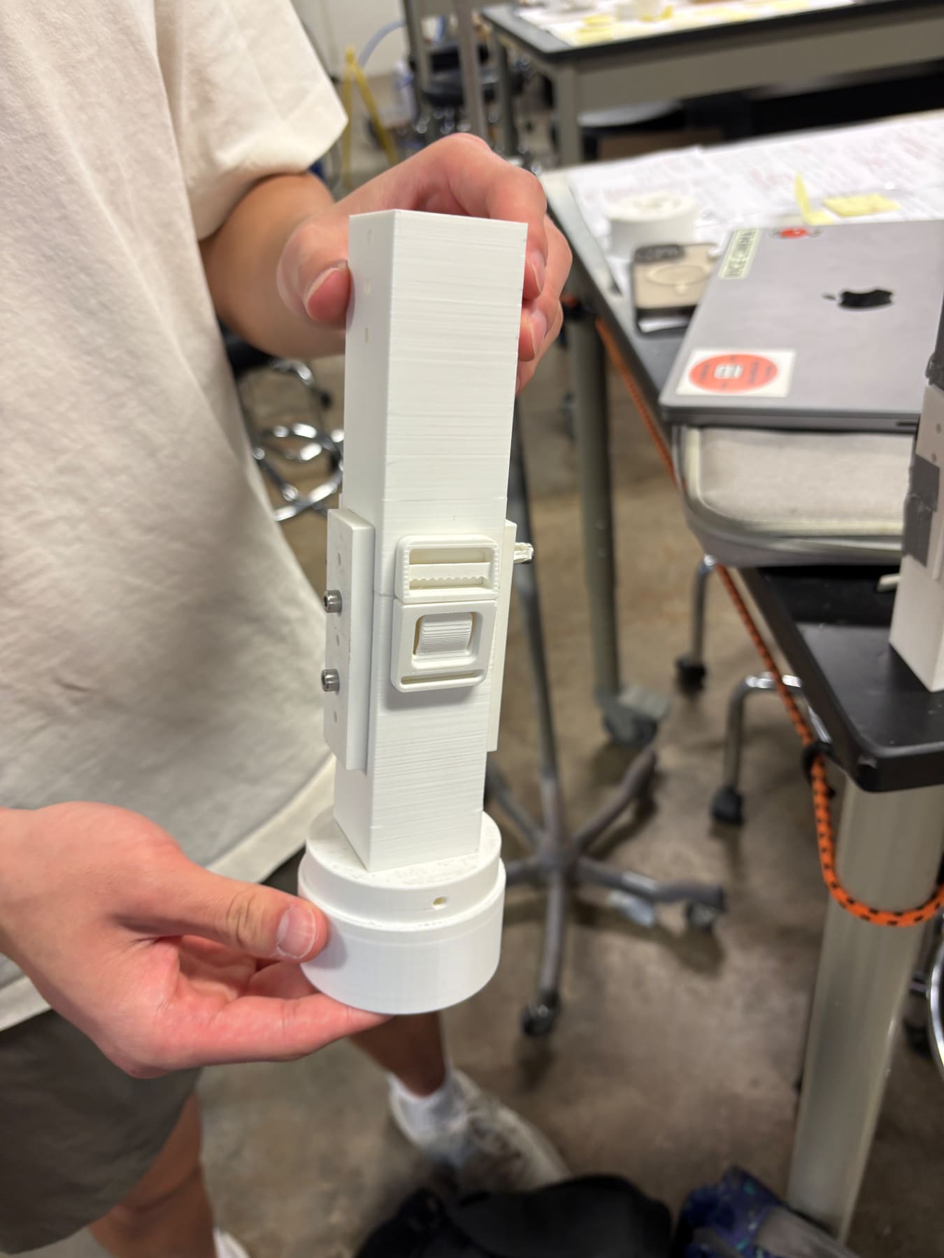
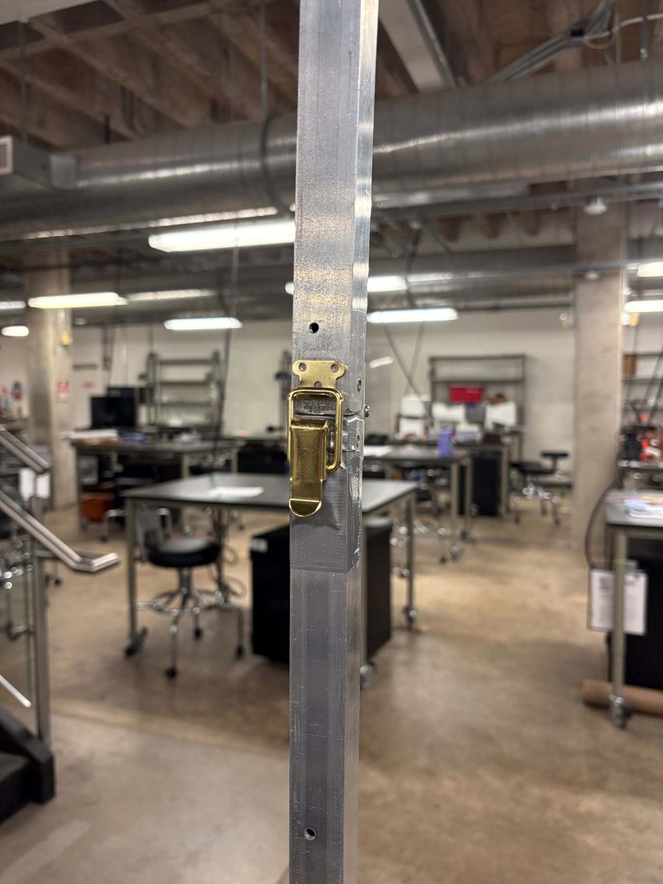
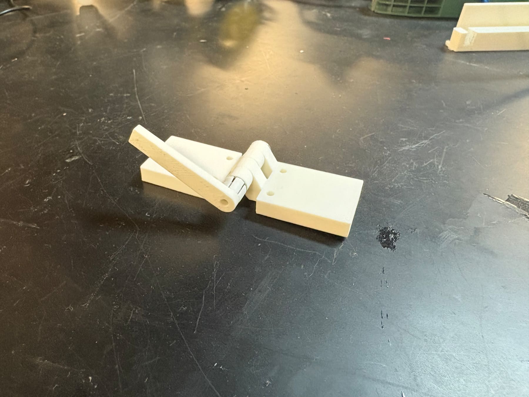
the omni mount’s hinge locks went through multiple iterations:
- bolt + nut. secure but required a wrench. too slow.
- 3d-printed clips. tool-free, but deformed under repeated use.
- wing nuts. tool-free, but loosened under vibration.
- cam lever clamps (final). quick-release, secure, no tools ✓
what i worked on
- low-fi. built the ball joint mechanism prototype using foam and a rubber balloon to test rotation.
- medium-fi. designed tripod-to-yagi attachments, developed the omni extension system, created the yagi handle, designed the stopping mechanism.
- testing. angle testing for the yagi (verified 90° with a protractor), clamp + hinge durability testing.
- CAD. modeled the clamp design in solidworks for mounting antenna to our system.
- field testing. went to the actual rice eclipse launch in midland to test the high-fi prototype in real conditions.
field testing results
real validation: deployed both mounts at an actual rice eclipse launch in midland, tx.
| CRITERION | TARGET | TEST RESULT | STATUS |
|---|---|---|---|
| stability | ≤8" sway | <6" antenna displacement | ✓ pass |
| rotation | 0–90° vertical | 90° achieved with protractor | ✓ pass |
| height | omni ≥10 ft | 11' 4" to antenna base | ✓ pass |
| ease of use | ≤30 min setup | ~30–40 sec per mount | ✓ pass |
| portability | ≤10 sq ft | ~1.5 sq ft each collapsed | ✓ pass |
| heat resistance | ≥180°F | PETG rated to 230°F | ✓ pass |
| modularity | ≥50% replaceable | yagi 50%, omni 57% | ✓ pass |
all 7 design criteria met or exceeded. the cam lever clamps reduced setup time from 42 min to under 1 minute per major assembly, a 98% improvement.
what i learned
technical
- full engineering design process: problem definition through field-tested solution
- systematic design methods: pairwise comparison, pugh screening, morphological charts, weighted scoring
- solidworks + 3d printing for functional components
- material selection for environmental conditions (heat, UV, strength)
- testing protocols that simulate real conditions, not just ideal lab scenarios
design process
- client feedback is critical. the backpack pivot showed how user insights reveal issues engineers miss.
- iteration reveals solutions. the hinge lock evolution proved the first working design isn’t necessarily the best.
- real-world testing is different. lab wind simulation couldn’t replicate unpredictable gusts and sandy terrain.
- systematic beats arbitrary. the structured EDP kept us from fixating on early ideas.
team collaboration
- worked in a five-person team with diverse skills and schedules
- imessage + 4x/week in-person meetings to coordinate
- agendas + weekly syncs to resolve communication issues
- everyone’s contribution matters, even when workloads appear uneven
team teletubbies
samer marmash, lilly smith, gabbi arenas, tyler fu, logan lu. EDES 120/220 engineering design, fall 2025.
client: rice eclipse rocketry team
NEXTFIG. 04 · 04 / 05custom electric bikeread it next ← BACK TO ALL PROJECTS