automating a chocolate production line
CASE CHOCOLATES · ENGINEERING TECHNICIAN · HOUSTON, TX · APRIL 2026 – PRESENT · ONGOING
sole engineer. i’m building it one module at a time. this is module one, and it runs.
overview
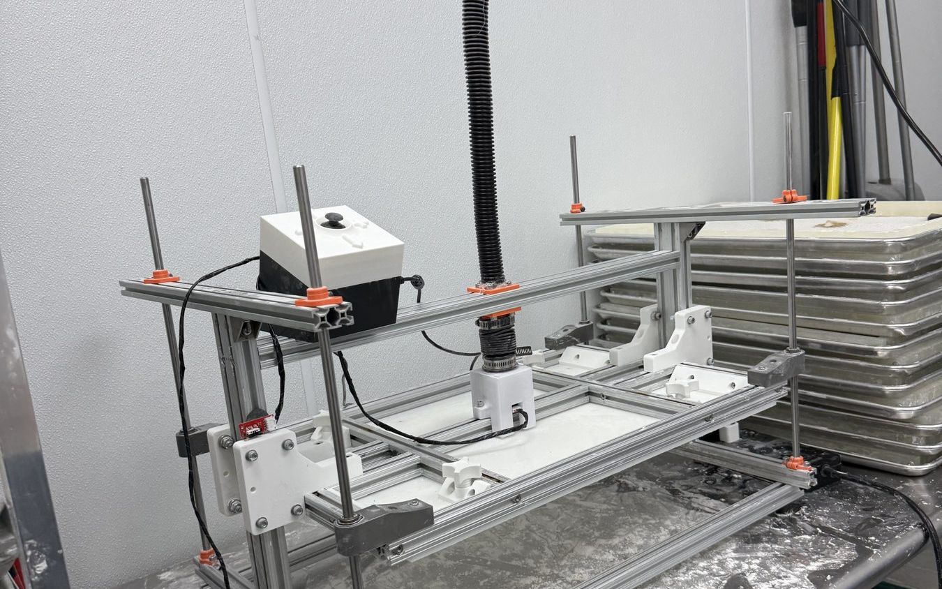
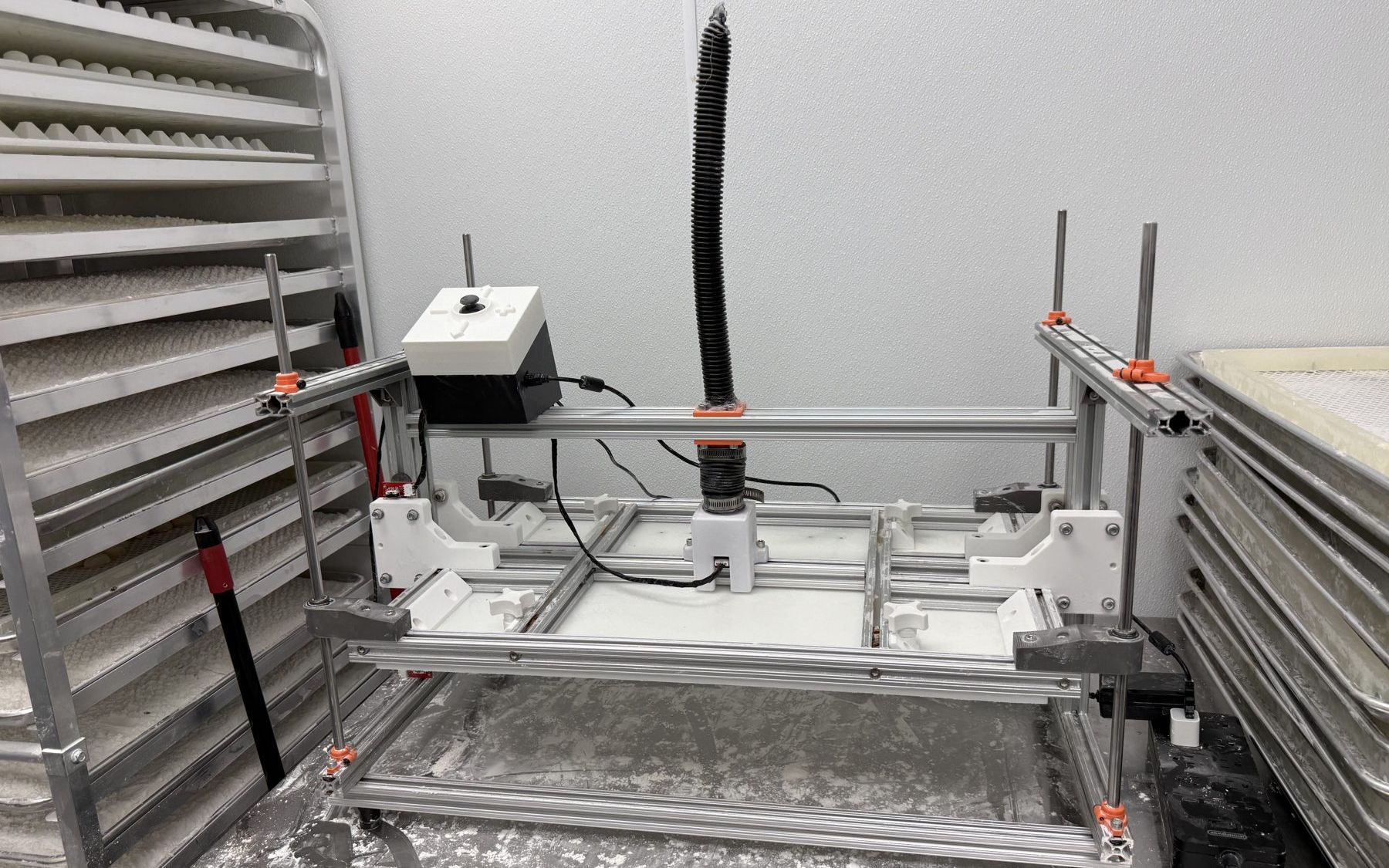
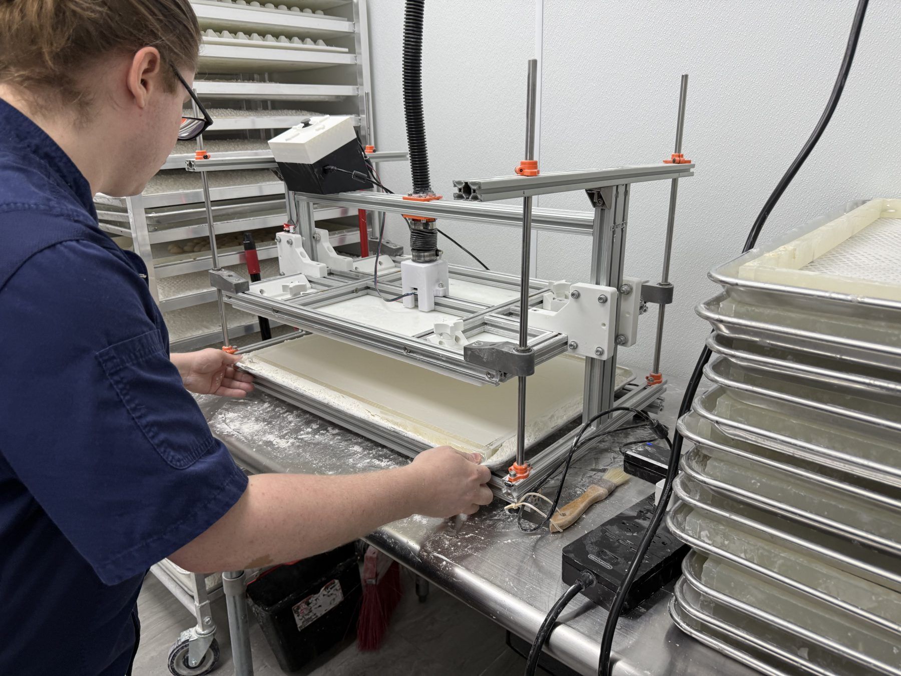
CASE Chocolates is automating its production line. The larger goal is an automated production system; the system is modular by design, because each subsystem has to deliver value on its own. The press , the machine that forms the product, is the first module, taken from prior static CAD to a working software-controlled prototype. The powder sifting and containment subsystem and the electronics enclosure are in flight. The remaining downstream modules are scoped, not built.
I am the sole engineer, end to end: CAD, prototyping, sourcing, motor and driver selection, wiring, firmware, and testing, building on prior CAD from two previous engineers.
see it run
the project on one page
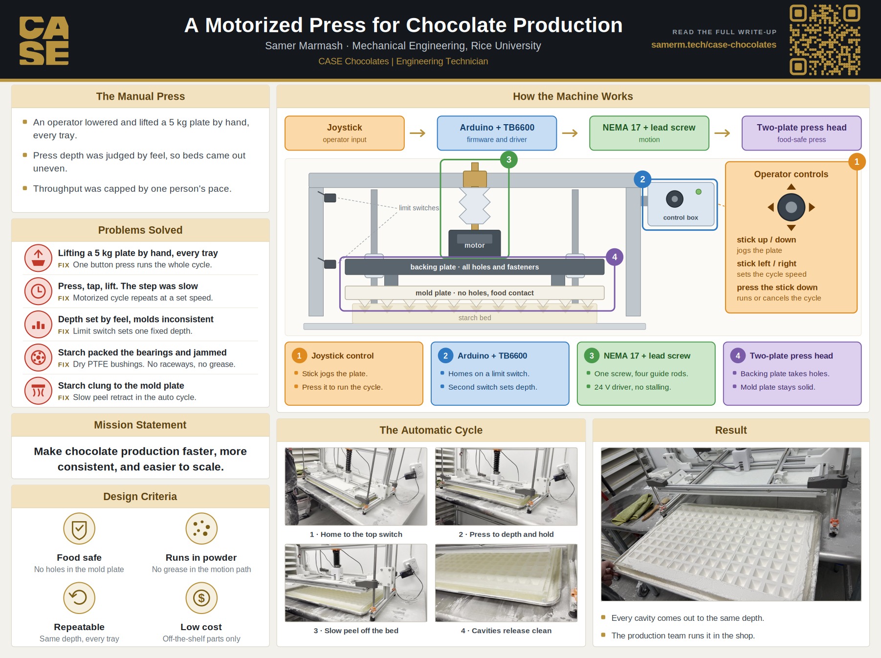
the poster version: the manual press it replaces, what each subsystem does, the operator controls, and the automatic cycle end to end. open it full size ↗ to read the detail.
- MODULE 01 · BUILT · RUNSmotorized press
- MODULE 02 · IN PROGRESSpowder sifting & containment
- MODULE 03 · IN PROGRESSelectronics enclosure
- MODULE 04 · SCOPED, NOT BUILTremaining downstream modules
WHAT’S SOLID IS WHAT EXISTS. WHEN THE NEXT MODULE SHIPS, ITS BOX MATERIALIZES.
the problem
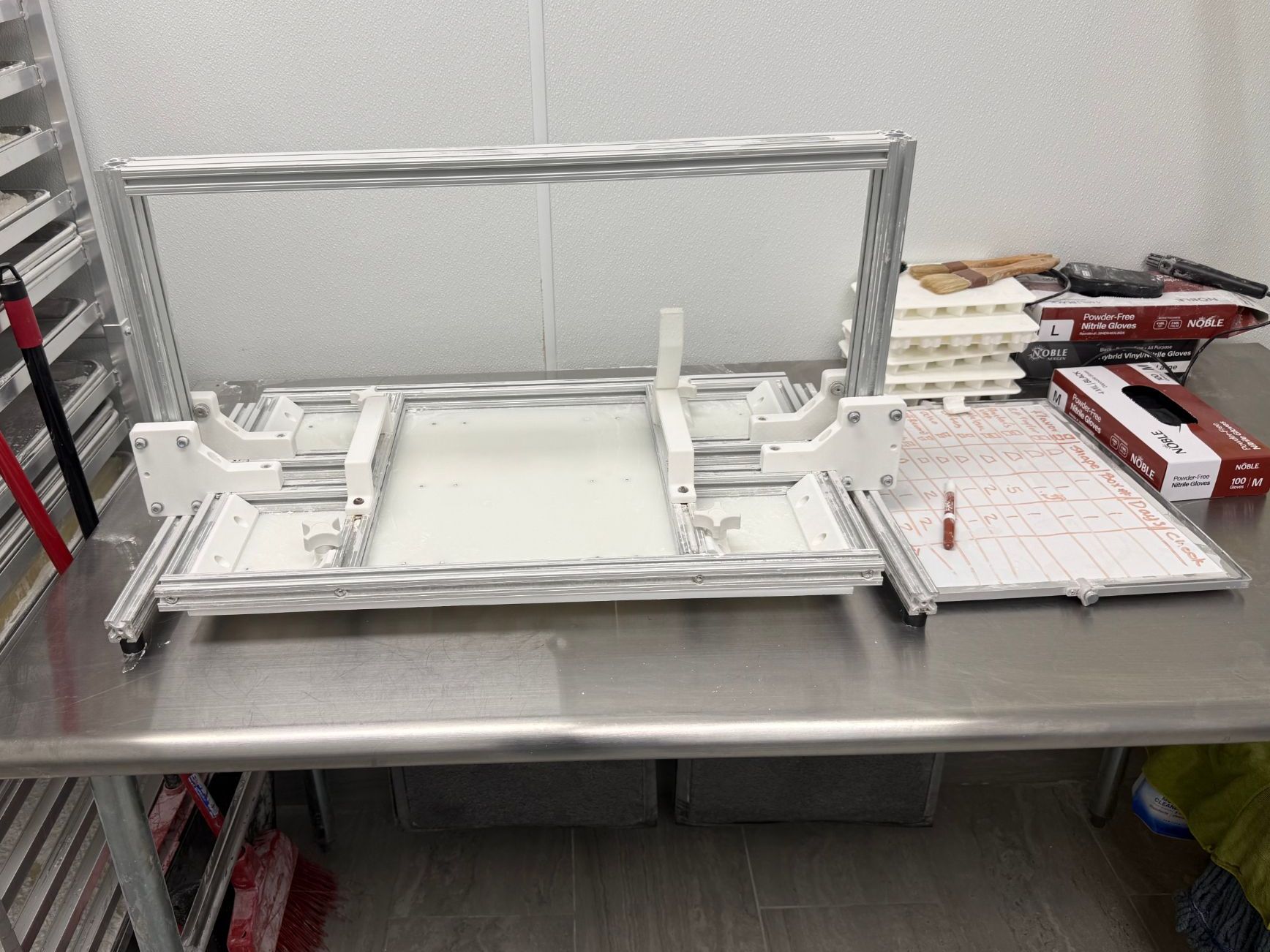
The press cycle was manual: an operator lowering and raising a heavy plate by hand, every cycle, with depth and dwell set by feel. The machine replaces that with a commanded cycle, home, descend to a fixed depth, hold, retract, repeatable to the step.
the constraints
drive architecture selection
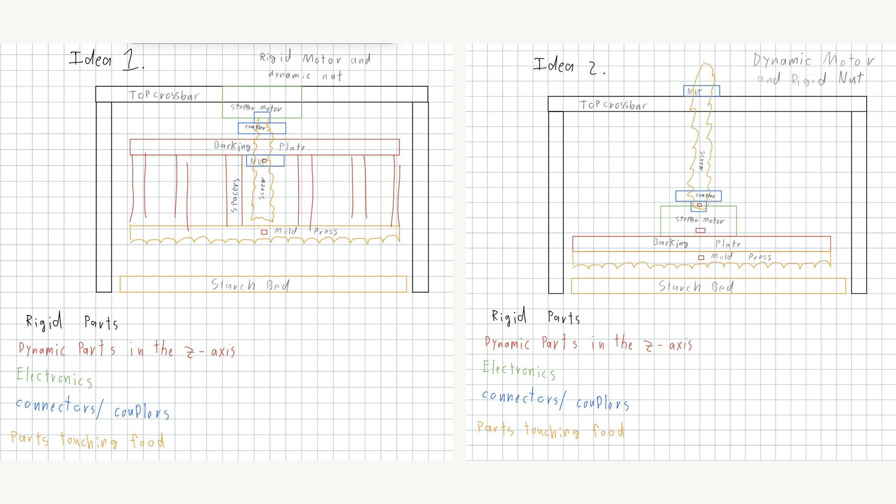
Four candidate architectures for moving the plate. TapClick between them, three were rejected for specific reasons, not preference.
the torque budget
LOAD        ~5 kg plate
REQUIRED    21.5 N·cm  ████████░░░░░░░░░░░░
AVAILABLE   40–60 N·cm (NEMA 17)
VERDICT     sized, not over-specified
The naive layout drives the plate from its center, which puts a threaded hole through the one surface that isn’t allowed to have one. Splitting the plate resolves the conflict without weakening either constraint: the backing plate carries every hole, every fastener, and the motor whose screw climbs through the fixed crosshead nut; the product-contact plate below it stays completely solid, bolted at the perimeter only. The backing plate also acts as a stiffener, resisting racking under off-center load.
contamination-resistant motion
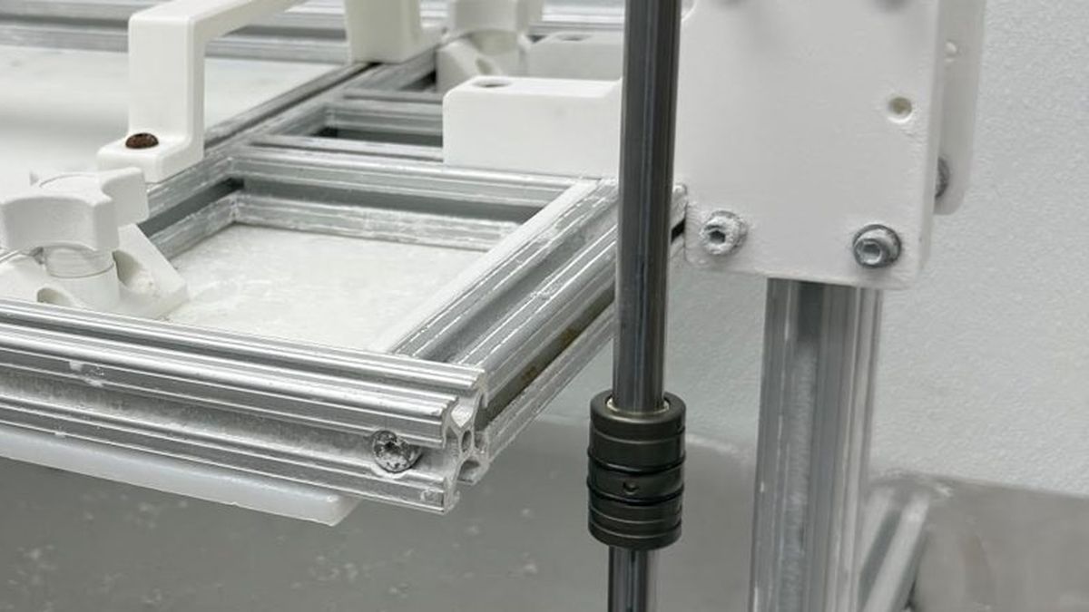
PTFE-lined self-aligning bearings
Cocoa powder ends the argument for rolling elements: an open ball bearing packs its raceways and seizes. The PTFE-lined bushings have no raceways to clog, run dry with no lubricant to foul, and tolerate 0.5° of misalignment.
the parametric bellows
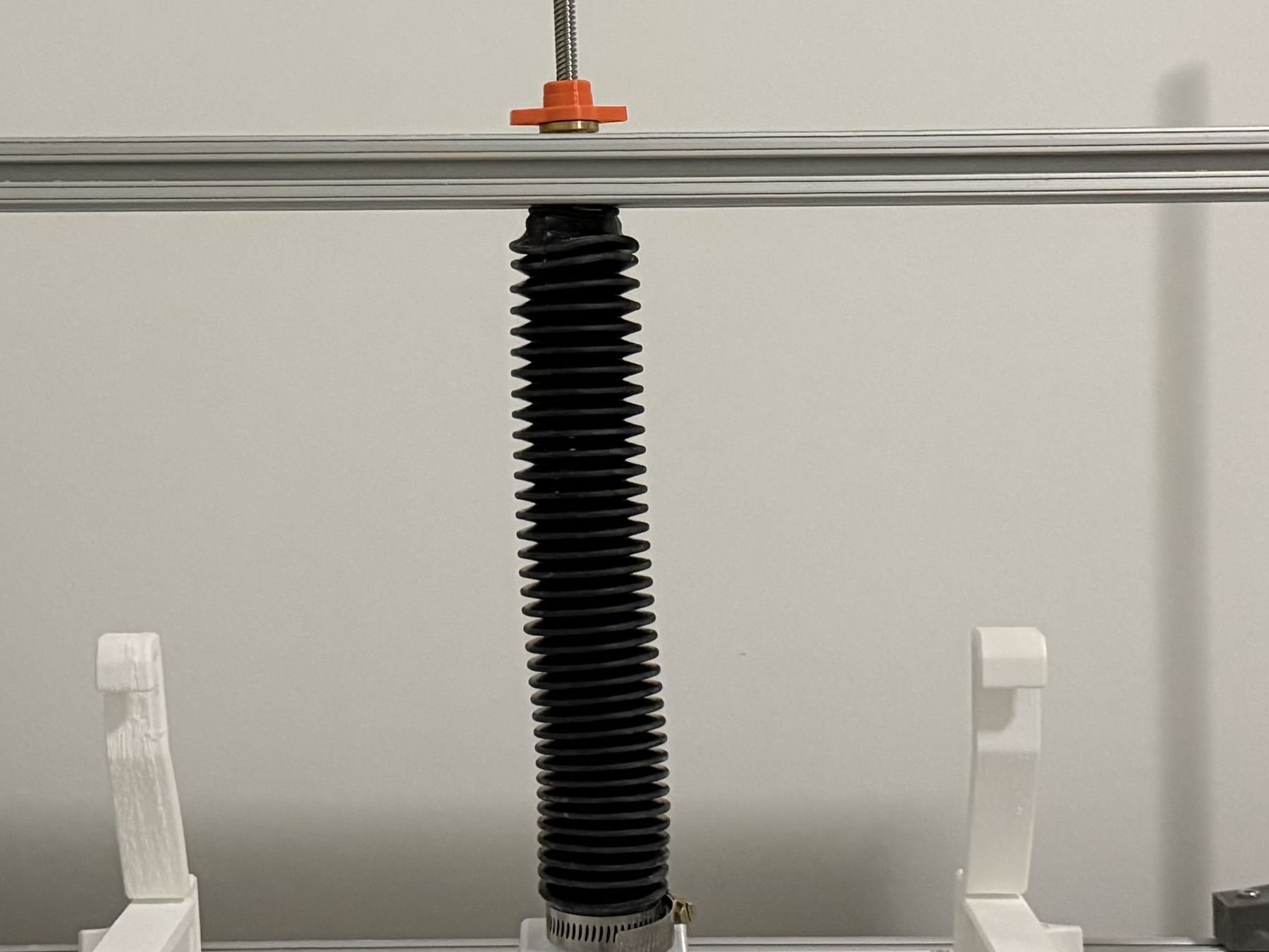
The lead screw needs a cover that lives between two moving planes and survives washdown, a part that doesn’t exist off the shelf at this geometry. A Python script generates it instead: target length and convolution count in, printable TPU geometry out, auto-split into segments when it exceeds the build volume.
hardened guide rods
GUIDE RODS   HARDENED STEEL Ø8 ON ALUMINUM SHAFT SUPPORTS
STIFFNESS    ~30× STIFFER THAN PRINTED PLASTIC
CREEP        NONE · GEOMETRY HOLDS UNDER SUSTAINED LOAD
electronics & firmware
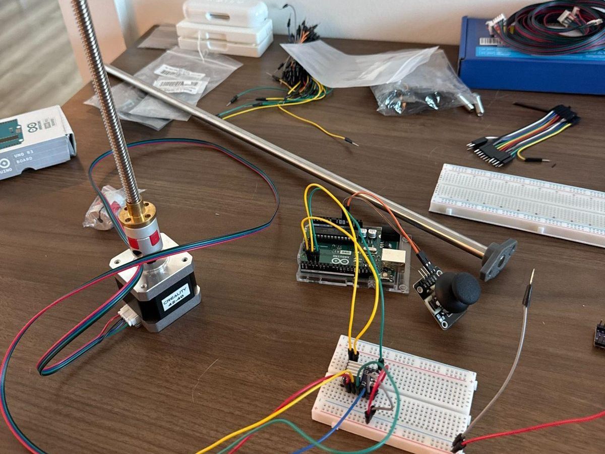
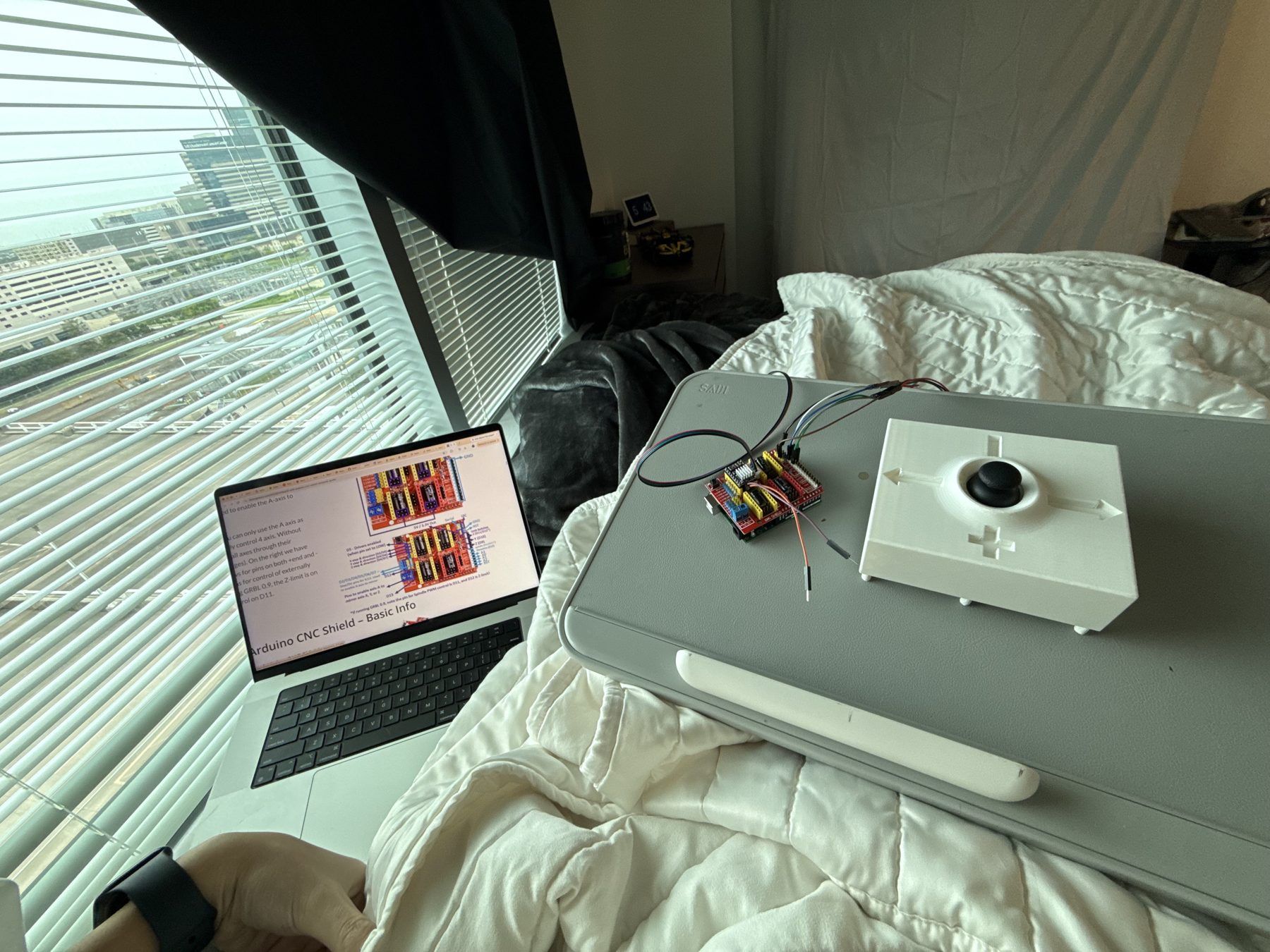
The control stack is deliberately plain: an Arduino running C++ firmware, a stepper driver, the NEMA 17, two limit switches for homing and interlock, and an analog joystick for manual jog. Open-loop, step-counted, sufficient because the load is known and the screw is self-locking.
const float PRESS_DEPTH_MM= 12.4;const float PRESS_SPEED= 48.0; // mm/sconst float ACCEL= 220.0; // mm/s²const bool JIGGLE_RETRACT= true;THIS IS THE REAL FIRMWARE’S SETTINGS BLOCK. A NON-PROGRAMMER TUNES THE MACHINE HERE WITHOUT TOUCHING CONTROL LOGIC · DRAG A SLIDER AND THE MACHINE RETIMES MID-CYCLE.
the acceleration-ramp fix
The first firmware commanded the target step rate in one jump. A stepper’s torque collapses if the rotor can’t follow the field; above ~50 mm/s the motor stalled and silently lost position, the failure mode open-loop control cannot tolerate. The fix is a trapezoidal velocity profile: ramp up, cruise, ramp down.
powder sifting & containment · electronics enclosure
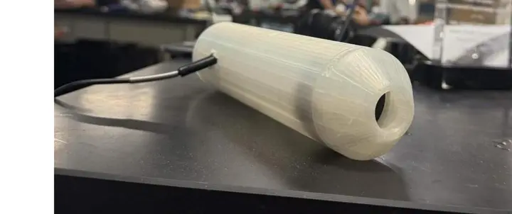
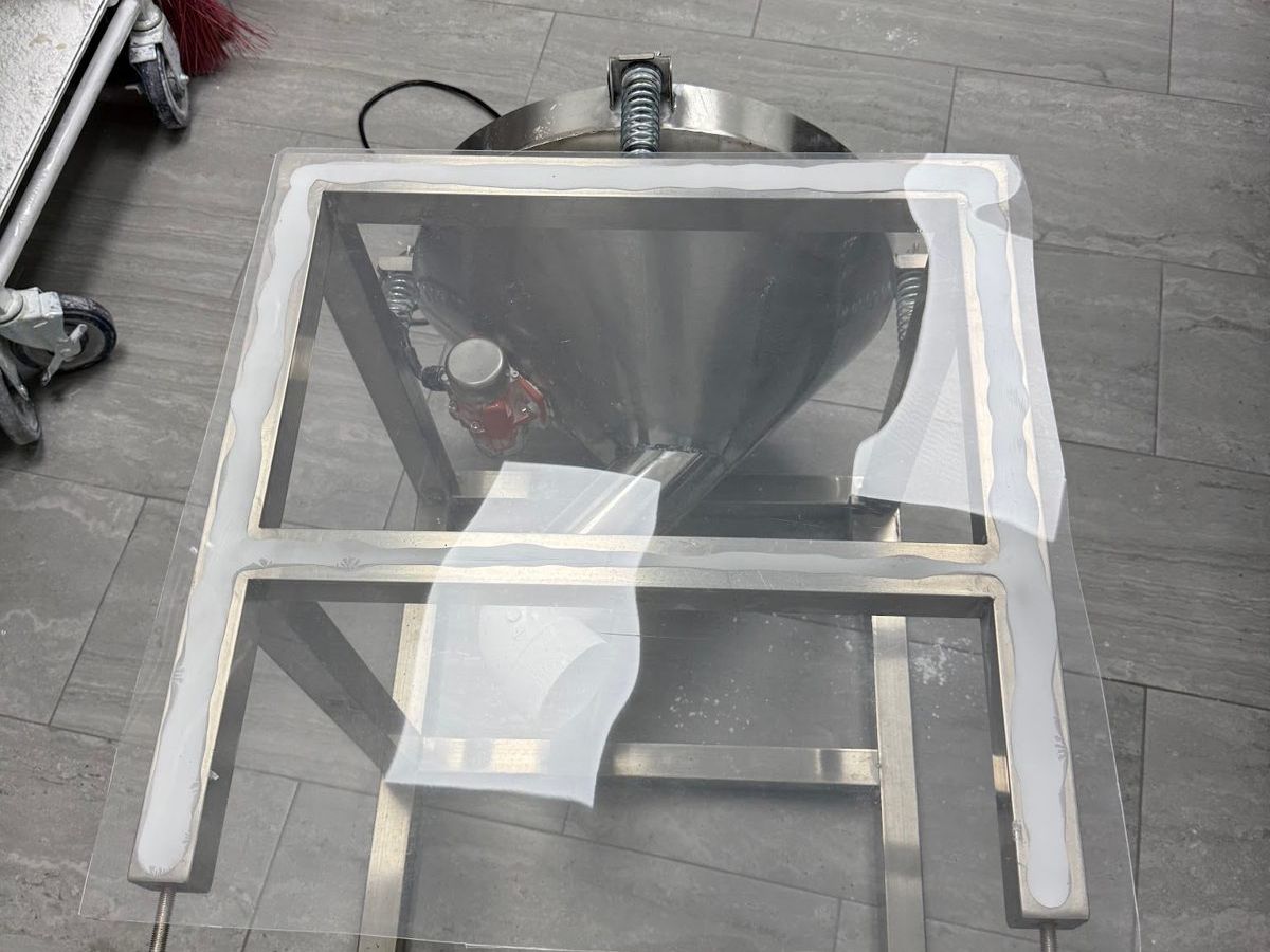
Sifting and containment. A sealed enclosure with a hinge and latch for washdown access, and a fixed brush that levels the powder bed at plate height, geometry doing the job instead of an extra actuator.
Electronics enclosure. No vents, deliberately: the driver runs below its thermal limit, so venting would only admit powder and moisture. The revisions below are the cutout geometry converging on the final component layout.
engineering judgment
DECISION LOG · INSTINCT → ANALYSIS → CALL
- THE INSTINCT
- friction, add a coating to the plate.
- THE ANALYSIS
- the product released cleanly on approach and stuck only on retraction. that's not friction, it's suction. a flat plate lifting off a soft surface pulls a vacuum, and a coating does nothing about a pressure differential. a fundamentally different problem than the one the symptom suggested.
- THE CALL
- vacuum release plus a programmed jiggle-retract (±0.4 mm, 3 cycles), not surface treatment.
- THE INSTINCT
- the bearing is wrong, redesign it.
- THE ANALYSIS
- the binding appeared while testing on a single guide rod. one support point cannot react a moment, by definition, any off-center load must tilt it. the four-rod production geometry resists tilt through wide spacing, the way a table resists tipping.
- THE CALL
- keep the bearing. the test setup was the artifact, not the part.
- THE INSTINCT
- the board is fried, tear the circuit down.
- THE ANALYSIS
- logic rails were reading 3× the supply voltage, which no failure mode of the board could produce. the instrument was the suspect: the multimeter was failing. isolating the instrument before trusting it saved a teardown of a working circuit. separately: caught a 12 V supply outputting 4× rated voltage before it reached the electronics.
- THE CALL
- verify the measurement chain before believing the measurement.
- THE INSTINCT
- more force is safer, spec a bigger motor, add force feedback.
- THE ANALYSIS
- the plate's own weight supplies most of the press force. the motor's job is controlled positioning, not brute force. required torque came to 21.5 N·cm against 40–60 available from a NEMA 17, which is why open-loop stepper control with a fixed depth target is sufficient and force feedback isn't needed.
- THE CALL
- NEMA 17, open loop, fixed depth. sized, not over-specified.
- THE INSTINCT
- the plate binds on the guide rods, lubricate them.
- THE ANALYSIS
- food-safe lubricants exist, but grease plus airborne starch makes clumps, and the design premise of the entire motion system is that it runs dry. a fix that violates the premise is not a fix, it is a maintenance schedule. the real cause was geometry: off-center load tilting the bearings on the rods.
- THE CALL
- no lubricant. re-mounted the manual press's old wheel guides mid-frame to react the moment before it reaches the bearings. the plate glides, dry.
- THE INSTINCT
- the motor can't lift the plate at speed, buy the strongest NEMA 17 made.
- THE ANALYSIS
- the stall appeared only at speed and got worse as the driver warmed up. that is a thermal signature, not a torque ceiling: the old driver was folding back current as it heated. the torque budget said the motor was sufficient, and the budget was right.
- THE CALL
- same motor, bigger driver (TB6600) and a 24 V supply. full speed, no stall, zero dollars spent on motors.
- THE INSTINCT
- swap the actuator for a cable-and-pulley lift, much cheaper.
- THE ANALYSIS
- checked with the production team first and learned force is applied after the plate is fully lowered, and free-dropping the plate produces a defective result. the shortcut would have failed in production.
- THE CALL
- kept the actuator. asking first turned a wasted build into a half-hour conversation.
“asking first turned a wasted build into a half-hour conversation.”
two weeks in july
everything above is the design. this is the build, straight from the work log: the two weeks where the machine fought back, and then gave in.
JUL 16 · THE DIAGNOSIS
the plate binds on its guide rods. the culprit is geometry, not parts: any off-center load puts a moment on the plate, the moment tilts the bearings on the rods, and a tilted bearing is a brake. the plate has to stay level and the rods perpendicular, at all times, or nothing else matters.
JUL 20 · BRUTE FORCE
found two steel support bars, drilled them, then discovered they were never tapped. hand-tapped every hole. hours of slow, careful threading. bolted the bars on, ran the plate. still stuck.
JUL 23 · THE LOW POINT
the bushings i ordered to add surface area on the rods arrived, went on, and made it worse: extra friction, no extra stability. i was very close to giving up on the whole approach. the tempting shortcut was food-safe lubricant, and i refused it: grease plus airborne starch makes clumps, and the entire premise of this machine is that it runs dry.
JUL 24 · GLIDES LIKE BUTTER
the fix was not a new part. the old wheel guides from the manual press, re-mounted mid-frame on both sides, catch the moment before it ever reaches the bearings. ten hours at the bench: wheel guides on, big motor and screw in, nut mounts seated, limit switches wired. one problem left, the plate only rises at a crawl.
JUL 25 · IT WAS NEVER THE MOTOR
the stall showed up at speed and got worse as the driver warmed. that is a thermal signature, not a torque ceiling: the old driver was folding back current as it heated. a TB6600 driver and a 24 V supply from the university workshop, firmware re-tuned to match, and the plate comes up fast without a single stall. bellows on, full cycle test. it works, very well.
▶ WATCH THE PRESS RUN ↗JUL 26 · THE MANUAL
a machine is not finished when it moves. it is finished when someone who did not build it can run it. wrote the operator manual.
↓ OPERATOR MANUAL · PDFJUL 27 · FIRST STARCH
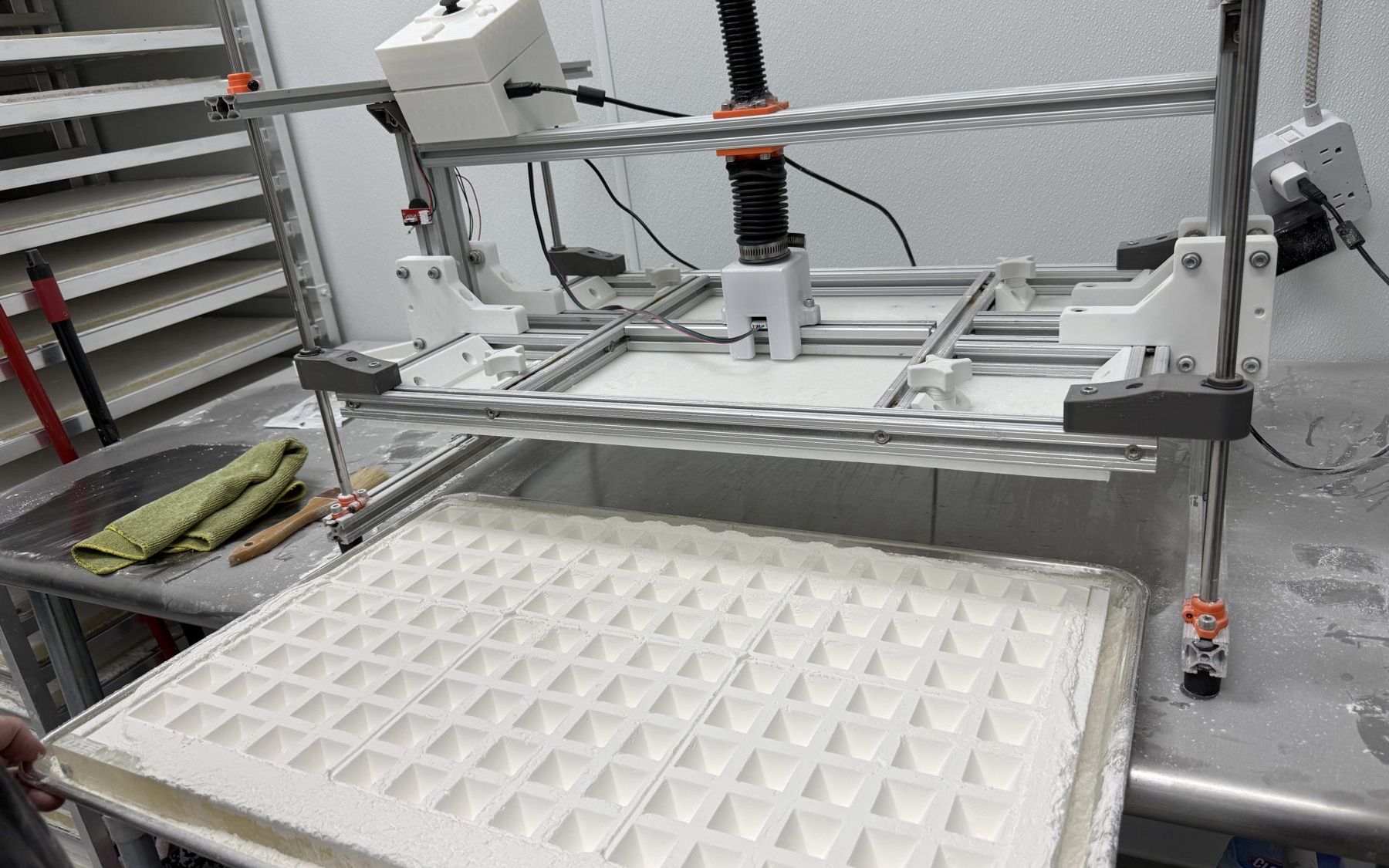
ran the machine on real starch for the first time. better than expected. the one flaw: product clings on retract. tried adding vibration and it made the sticking worse, which confirmed the suction theory, air cannot refill the gap under the plate fast enough. a slow peel at the end of the cycle helps; the tuning continues.
JUL 30 · FIRST FEEDBACK
aaron ran it and reported the press does not reach deep enough on some molds. the fix costs two metal rods: raise the starch bed instead of redesigning the press. permanent motor bar in, screw fully sealed inside the bellows.
AUG 03 · SETTLING IN
bed rods drilled and mounted, a bigger electronics box printed and installed on the frame. the machine lives at the shop now. next on the list: the sifter gets its hinge and latch.
where it stands
the press is real now. it homes, descends to a commanded depth, holds, retracts, and it has done all of that on actual starch, in the actual shop, with someone other than me at the joystick.
current work is refinement under production conditions: tuning the retract against mold suction with the slow peel, raising the starch bed so every mold pattern reaches full depth, and the sifter’s hinge and latch so the containment story closes.
that was the summer’s work: one module, from prior static CAD to a machine the shop runs without me. i’m still on through the fall, and the remaining three modules follow from here.
- MODULE 01 · BUILT · RUNSmotorized press
- MODULE 02 · IN PROGRESSpowder sifting & containment
- MODULE 03 · IN PROGRESSelectronics enclosure
- MODULE 04 · SCOPED, NOT BUILTremaining downstream modules